How High-Efficiency Cyclones Work

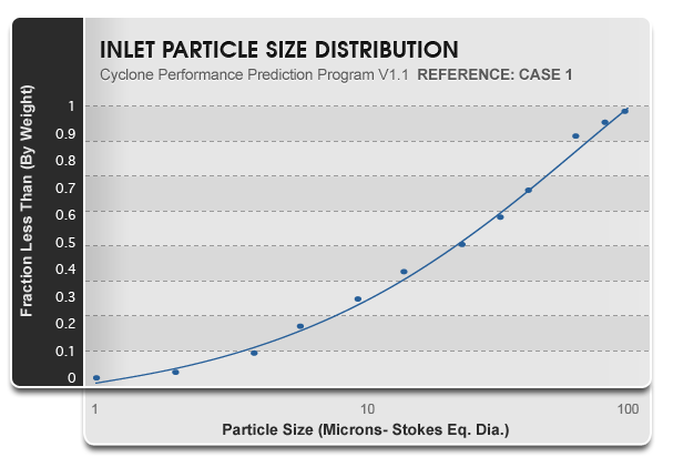
Inertial separators can be utilized to separate substances that have different inertial properties by subjecting the mixture to centripetal acceleration and taking advantage of the different response rates the substances will exhibit. While there are numerous styles of inertial separators, Reverse Flow Cyclones (RFCs) are often called “conventional cyclones” or “high-efficiency cyclones” and are the most common design utilized for the separation of particulate from a gas or fluid flow. (fig1)

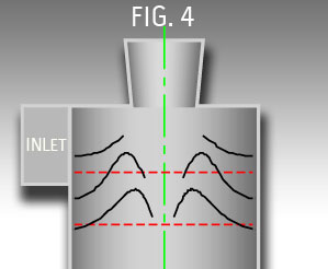
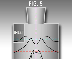
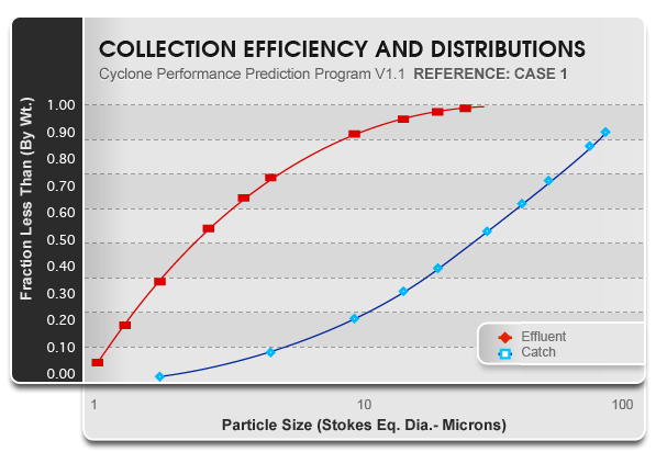
RFCs derived their name from the secondary gas flow pattern within the high-efficiency cyclone. The primary flow pattern is the spin, or rotational flow, caused by the arrangement of the inlet near the top of the device. While the mixture is spinning and the particulate is being centrifuged towards the wall of the device, it must travel first downward along the outside of the vessel then reverse direction and travel upward in the center to exit the gas outlet pipe at the top. This flow pattern is often described as a double vortex consisting of an outer and an inner vortex. In reality though, the flow is a single vortex consisting of a continuous flow stream where the so called outer vortex is pulled within itself from the bottom up. (fig2)

When designed properly, a cyclone will concentrate the particulate along the wall of the device and then transport it to a collection area at the bottom where it is separated from the returning gas flow. To separate a particle from a gas stream, we must not only have an adequate amount of centrifugal force applied to the mixture over an adequate amount of time for the particle to move to the wall of the cyclone, but we must be able to transport the particle to a collection point and successfully get it to stay within the collection zone. One of the most important design tools available to affect cyclone performance is that of residence time within the cyclone. Residence time is a term describing the amount of time that is available for a particle to reach the collection zone of the cyclone before the flow has exited the cyclone.  Increasing cyclone diameter and length increases the residence time. The increase in the available time for collection of particles often results in an increase in the total collection efficiency despite some reduction in centrifugal force resulting from the increase in cyclone diameter.   It is important to keep in mind that while the centrifugal force exerted on a particle that is near the outside wall of the cyclone will be lower if the diameter of the cyclone increases, the most critical point for the separation of particles is the velocity and radius of travel at the core of the vortex flow. Here the velocity and radius is primarily a function of the inlet and outlet velocities and geometry.

The physics of inertia are well known and it is relatively simple to predict the forces required to move a particle to the wall of the high-efficiency cyclone within a given residence time. This is described as theoretical collection. In practice, many particles that subsequently escape the high-efficiency cyclone and are emitted were transported to the wall of the device and into the collection area where they were subsequently re-entrained in the escaping gas flow (fig3).

For these reasons, high-efficiency cyclone design is very complicated and it is impossible to accurately predict particle separation from purely theoretical models. The most accurate technique for predicting cyclone performance is the Theoretical-Empirical Method. This method utilizes the empirically measured performance of a cyclone of some geometry then uses the known effects of gas and particle physics to alter these results for alternative operating conditions and size.

There are two primary measures of cyclone performance. These are;

  1. Pressure drop which is defined as the difference in gas static pressure between the inlet and outlet of the high-efficiency cyclone.
  2. The size efficiency curve (SEC) which is a function or curve that describes the fraction of particles collected verses particle size and density.

As described previously, there are two major aspects of flow within a high-efficiency cyclone to consider: a) the rotational flow or primary flow pattern (fig4) and b) the axial flow or secondary flow pattern (fig5).

2.1 Rotational Flow

The rotational, primary, flow pattern is used to impart greater inertia or centrifugal force on the particles than the gas molecules. The goal is to create an adequate centrifugal force field so that particles can not cross into the central core of the high-efficiency cyclone where the gas is travelling upward to exit the device. Another way to think of this is to consider the centrifugal field as a barrier or boundary much as we think of particle filtration where a particle can not pass through a media whose pore size is smaller than the particle. The factors that affect the centrifugal force placed upon a particle are described by the equation for centrifugal force:

Fc = Vt2/r • M where;
Fc is the centrifugal force, Vt is the tangential velocity, M is the particle mass, r is the radius of the circular path at the point of measurement

It is obvious from this equation that greater tangential velocity, greater mass, and a smaller radius of travel all result in greater centrifugal force. We can ignore the mass of the particle for this consideration since it is what it is. On the other hand, tangential velocity and the radius of the path of travel are both variables that we can utilize to affect cyclone collection efficiency.


FIG 6

fig6

We can increase tangential velocity by increasing the tangential component of the high-efficiency cyclone inlet velocity as well as by increasing the radial distance between the inlet and the inner core of the high-efficiency cyclone. In high-efficiency cyclone rotational flow, the tangential velocity increases from its initial tangential velocity as it moves to a tighter radius of travel due to a conservation of momentum (fig6). In the area where the velocity increases to conserve momentum, the flow is called a free vortex. At some point the viscous forces on the gas molecules prevent the increase in tangential velocity and the gas rotates as solid body or fixed or forced vortex. Therefore we can increase centrifugal force by not only increasing the inlet velocity but also by

  1. reducing the diameter of the outlet pipe
  2. reducing the high-efficiency cyclone diameter
  3. increasing the radial distance from the inlet to the center of the high-efficiency cyclone

It is important to understand though that not only do these rules apply to the particulate that is in the flow stream but to the gas itself. The resulting pressure gradient that is formed within the gas flow is the single biggest component of high-efficiency cyclone pressure drop. In other words, the greater the centrifugal force the smaller the particle we can collect but we pay for it in increased power consumption in the form of pressure drop.

2.2 Axial Flow

The axial, or secondary, flow pattern is downward along the outside of the high-efficiency cyclone assembly and upwards in the center. This flow pattern is critical to the performance of a high-efficiency cyclone since we pneumatically transport particles from the upper portion to a collection receiver or discharge point.

A common, but inaccurate, description of how a high-efficiency cyclone works often goes, “the particles are thrown towards the wall of the high-efficiency cyclone where they are slowed by friction and then fall into the receiver due to gravity.” This statement is almost completely wrong. While the particles do slow somewhat due to friction when they reach the wall of the high-efficiency cyclone, the flow patterns and forces placed upon the particles are many times greater than gravity. Often larger greater mass particles are transported to the receiver more slowly than small particles due to the particle’s inertia acting upon the sloped surface of the cyclone cone. Collected particles are pneumatically transported to the bottom of the assembly in a fraction of the time required for settling by gravity.

Our goal in high-efficiency cyclone design is to “land” the collected particles on the bottom surface of the receiver with the proper tangential and axial velocities so that it remains in the collection zone and is not re entrained in the escaping gas flow. If the axial velocities or angle of attack are too great, re- entrainment goes up. If they are too low, axial particle flow can become stagnant at some elevation in the high-efficiency cyclone. These particles will accumulate until the mass get large enough to disrupt the flow and they fall by gravity or they may be continuously re-entrained into the escaping gas flow. In either case, the probability of a plug occurring and unacceptable levels of cone erosion go up.

Since high-efficiency cyclones typically operate over a range of operating conditions as well as particle size, a dust receiver or vortex breaker is commonly used to reduce particle re-entrainment.

The single most difficult issue for proper high-efficiency cyclone for proper cyclone design is to accurately predict performance. The two main components of performance are the pressure drop and the size efficiency curve (SEC).

At Heumann Environmental Company (HEC), we utilize the Theoretical-Empirical Method for achieving an unmatched accuracy of performance prediction while allowing the greatest possible range of design customization. This insures that HEC high-efficiency cyclones meet your performance requirements while providing the desired cost benefit. Our unique Performance Prediction Model is built upon our proprietary independent research, almost a century of published research, and those theoretically based correlations that have been proven accurate by extensive independent research.

Figures 7,8, and 9 show the input data and subsequent design results for a particular high-efficiency cyclone selection. Figure 7 represents the basic input process data as well as the critical dimensions for the cyclone selected. Figures 8 and 9 provide the predicted performance for the cyclone including pressure drop and the SEC presented in tabular form and graphical form.  All of the results are shown at zero and the specified dust load since the particulate loading affects both of these results.

Fig 7: Cyclone Performance Prediction Program V1.1 REFERENCE: CASE1

Cyclone Style
Inlet Type Involute
Tapered Outlet No
Cyclone dimentions IN FT CM M
Inlet Height (A) 14.000 1.167 35.560 0.356
Inlet Width (B) 6.500 0.542 16.510 0.165
Body Diameter (D) 28.000 2.333 71.120 0.711
Body Length (L) 38.500 3.208 97.790 0.978
Cone Length (C) 80.500 6.708 204.470 2.045
Lower Outlet Pipe Diameter (De) 10.000 0.833 25.400 0.254
Discharge Diameter (Dd) 12.000 1.000 30.480 0.305
Inlet CL Radius (Ri) 17.750 1.479 45.085 0.451
Material Thickness 0.250 0.021 0.635 0.006
Outlet Pipe Length (S) 17.500 1.458 44.450 0.445
Upper Outlet Pipe Diameter (Du) 10.000 0.833 25.400 0.254
Inlet Conditions
Gas Flow Rate 1851.2 Ft3/m 3547.0 M3/H
Gas Density 0.075 Lb/Ft3 1.201 Kg/M3
Gas Viscosity 1.203E-05 Lb(mass)/Ft- 1.790E-05 Kg/M-S
Temperature 70.0 °F 21.1 °C
Pressure (Guage) 0.00 Lb/In2 0.000 Kg/Cm2
Particle Loading 235.00 Gr/Ft3 537.77 G/M3
Particle Specific Gravity 2.30

Fig 8: Size Efficiency Curve

Particle size (Stokes Eq. Dia.) % Collection (by weight) at zero dust load % Collection (by weight) at specific dust load
1.25 14.36 32.20
3.75 73.40 78.94
6.25 85.03 88.14
8.75 90.56 92.52
11.25 93.78 95.08
13.75 95.89 96.75
17.50 97.98 98.40
25 99.31 99.45
35 99.67 99.74
45 99.67 99.90
55 99.99 99.99

Fig 9

fig9

Contrary to our normal intuition, increased particle loading causes a decrease in high-efficiency cyclone pressure drop. It is correct that the particles experience friction when sliding along the wall of the high-efficiency cyclone but it must be remembered that frictional losses (both gas and particle) are a minor part of the total pressure drop. The single biggest component of pressure drop is the pressure gradient generated by the rapidly spinning mixture in the high-efficiency cyclone. By slowing the tangential velocities, pressure drop is reduced. While a reduction in tangential velocity would seem to indicate a reduction in centrifugal force which would cause a decrease in particle collection, the opposite is true in practice. As particle loading goes up, particle to particle interaction goes up and the agglomerates behave as larger particles.

3.1 Total Collection Efficiency

In most cases the SEC is a relatively meaningless piece of information to the high-efficiency cyclone user and what is really desired is an accurate prediction of total amount of particulate that is collected or emitted and/or the size of the particles in these fractions.

While not trivial, the calculation of what is collected or emitted is a relatively simple mathematical operation once the aerodynamic characteristics of the incoming particulate are know. For a more complete understanding of this and the appropriate terminology, please see “Before you design an inertial separators: Measure your dust’s aerodynamic particle size”, Bill Heumann, Powder and Bulk Engineering, April 2002.

Fig 10

fig10

In Fig 10 we show a typical inlet particle size distribution (PSD).  In Fig 11 we show the graphical representations of the catch and effluent.

Fig 11

fig11

In Fig 11 we show the resulting prediction of the percent of the inlet feed that will be collected, the emission rate, and graphical representations of the PSDs of the catch and effluent.